Have a Power Transformer Question?
Need to know how transformers work? Need to dust up on your electrical circuitry understanding? Some of the below information will help you determine what type and size transformer you may need. If you have a question that is not listed here, please contact us – we’re always happy to help.
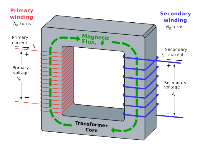
A transformer is a simple device that transfers electrical energy from one circuit to another by means of magnetic induction. An alternating current (AC) in the primary circuit creates a changing magnetic field in the iron core. This magnetic field induces a changing (AC) voltage in the secondary circuit.
Connecting a load across the secondary results in an AC current flowing, transferring electrical energy from the primary circuit to the secondary circuit.
The output voltage of a transformer is determined by the ratio of turns between the primary and secondary. The secondary induced voltage Vs, of an ideal transformer, is scaled from the primary Vp by a factor equal to the ratio of the number of turns of wire in their respective windings. Thus the voltage ratio can be expressed:
For example, a transformer with 240v input and 24v output will have about 10 times more turns on the primary than the secondary (disregarding losses).
The number of turns on the primary determines the strength of the magnetic field created in the core. This is called the flux density.
A three-phase transformer operates just like three of the above single-phase transformers. For convenience, they may be wound sharing the three legs of one iron core.
A power transformer may be specified as follows:
- Single phase or three phase input voltage and frequency
- Output voltage or voltages (if more than one output)
- Output current or VA (Note: VA = volts V x amps A)
- For a three-phase transformer, the connection – such as Yd1 or Dy11 (see Question 3)
- Open type or encased – specify required IP rating (IP = Ingress Protection)
- Any special features you require, such as an electro-static screen, terminal blocks, solder tags etc.
Transformer power is usually rated in VA. VA is simply the product of voltage V x current A.
A transformer rated at 240v 50Hz / 24v @ 150VA has a full-load output current found by dividing the VA by the output current = 150/24 = 6.25A. Similarly, the same transformer will have a primary full-load current of 150/240 = 0.625A.
Power is measured in Watts, using the symbol W (named after James Watt – the inventor of the steam engine). In a DC (direct current) circuit W = VA.
This is also true in an AC circuit with resistive elements only (no inductance or capacitance).
Inductors and capacitors cause the current in an AC circuit to be out of phase with the voltage (current waveform leading voltage for capacitors and lagging for inductors). The phase angle between voltage and current waves is called the power factor and expressed as cos (for most practical transformer-related applications cos is usually 0.8).
So, in summary, in an AC circuit: VA = Watts/power factor
E.g. A three-phase motor rated 10KW (10,000W) with 0.8 p.f. requires 10/0.8 = 12.5 KVA
Power used to be stated in horsepower.
One horsepower (HP) = 0.746KW (or 746W)
So a motor rated 10HP = 1.34 x 10KW = 13.4KW
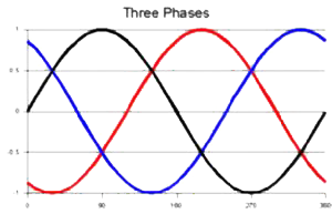
Three-phase power consists of three single-phase power systems all 120° apart (see diagram).
Three-phase power is particularly useful for applications such as motors, because three-phase motors are self-starting, and more efficient than single-phase motors.
Electrical power is usually supplied as three phase, and single-phase circuits are connected to different phases to balance the load evenly over the three phases.
Power is measured in Watts (W) or kW (One kW = 1000W)
Single-phase power: W = V x A x cosΘ (cosΘ is the phase angle between voltage and current waves and usually 0.8) – see Q4.
Three-phase power S = 1.73(V x A x cosΘ)
E.g. How much power does a three-phase motor 415v rated at 5A, with p.f. = 0.8, produce?
Power S = 1.73 (V x A x cosΘ )
= 1.73 (415 x 5 x 0.8)
= 2.88 KW
The term “regulation” refers to voltage regulation of a transformer.
The voltage regulation is the difference between the open-circuit output voltage of the transformer and the full-load output voltage. This is usually expressed as a percentage.
Regulation of a small PCB transformer may be as high as 20 per cent, with a power transformer up to 1000VA usually having regulation 5 per cent. A larger transformer will have even lower regulation, with about 3 per cent regulation being typical for transformers around 10KVA and about 1 per cent for 500 KVA transformers.
For example, a typical 100VA control transformer rated at 24v full load (approx. 4A) may have an open-circuit output voltage of 25.2v
Voltage Regulation Voltage Regulation = (Vo/c – Vfl) / Vfl = (25.2 – 24) / 24 = 5%
In Australia we have a power system that operates at a frequency 50Hz. This means that the full sinusoidal voltage waveform repeats 50 times each second (Hertz = cycles per second).
Equipment such as transformers and motors rated at 60Hz may not operate safely at 50Hz, due to higher core losses and possible core saturation due to increased flux density. Equipment rated 50/60Hz is, of course, safe to use on 50Hz.
Transformers designed to operate at 50Hz will operate perfectly well at 60Hz (usually with slightly lower core losses).
Some electrical equipment will not operate satisfactorily at 50Hz if designed to run on 60Hz – for example, a synchronous motor will run about 20 per cent slower on 50Hz, which may be a problem in a clock or timer.
Inrush current or input surge current is the maximum instantaneous current drawn by electrical devices (transformers, motors etc.) when first turned on.
This inrush current only occurs during the first few cycles after turning on, and will have greatly reduced after about 80mS (four cycles).
An inrush current as high as 16 x full-load primary full-load current would be a peak value that would only occur for about half of one cycle at switch on. A multiple of 10 x full-load primary current would be a realistic maximum RMS current over the first few cycles.
E.g. a three phase 50KVA transformer with a 415v primary, which has a full-load primary current of 70A. Inrush current = 10 x 70A = 700A over the first few cycles.
Cables, circuit breakers and associated devices must be capable of withstanding these high inrush currents.
An auto transformer is a single winding transformer, providing a smaller and cheaper alternative to a double-wound transformer. Auto transformers are useful when isolation from the input mains is not required.
The greatest saving in using an auto transformer is when the input and output voltages are close in value.
E.g. a three-phase auto transformer with 415v input / 380v output rated 20KVA would be about the size of a 2KVA isolation transformer (just 10 per cent of the size of a 20KVA isolation transformer).
The same savings can be achieved with single-phase auto transformers, with a 240v input / 220v output rated 500VA. This could be made equivalent in size to a 50VA isolation transformer.
Imported equipment designed to operate on an overseas voltage can often be adapted for use on local Australian power (240v single phase, 415v three phase). This may be a much cheaper alternative than buying an isolation transformer, or having the equipment rewound.
Three-phase auto transformers 415v input / 200v output are perfect for operating electrical equipment imported from Japan. As the ratio of output to input voltage is about half, an auto transformer to run such equipment will be about half the size of an equivalent isolation transformer.
Australian Standard AS 3000 – 1986 (Clause 4.28.4) requires auto transformers that change voltage by more than 25 per cent to be an integral part of the equipment they are powering. This can be achieved by hard wiring the equipment to the output of the auto transformer.
A so-called “outdoor transformer” is simply a transformer that is designed to operate in an outdoor environment. Many transformers operate indoors, so require less protection, such as an IP23 enclosure (see IP Ratings), or even IP00 (open-type transformer) if located inside a switch-board enclosure.
However, if operating outside, an outdoor transformer is usually required, which would have at least IP55 or higher rating. This type of enclosure is also often referred to as a weather-proof enclosure. While there are fans and ducts that are rated IP54 (and sometimes higher), we prefer to supply our outdoor transformers within a fully sealed IP65 enclosure. Such an enclosure reliably prevents dust and water from entering.
People often buy electrical equipment such as power tools and kitchen appliances from the USA without realising that these appliances cannot be plugged directly into Australian power sockets.
The US operates on a different power system to ours, with US single phase appliances running on between 110v and 120v at 60Hz.
DON’T DESPAIR! Most such appliances can be safely operated in Australia if you use a step-down transformer to convert the voltage for 240v down to 110v (see Q8 about the problem of 60Hz).
We stock a range of step-down transformers designed to power US appliances. These transformers are housed inside a powder-coated steel enclosure, usually with a lifting handle, and fitted with one or two US 110v sockets so your US appliance can be plugged straight into it. Fuses and thermal overload sensors provide protection from accidental overload or short circuits.
Similarly, we stock transformers designed to power Japanese 100v appliances with Japanese-style sockets.
We also make a range of three-phase auto transformers 415v / 200v and 415v / 220v to power larger three-phase equipment imported from the US and Japan.
Any More Questions?
To help us provide you with the best solution to your needs please contact us


